FEA Analysis
About
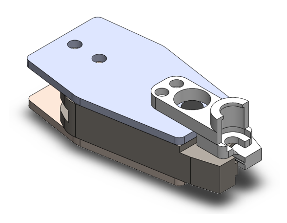
My senior design project at the University of Saint Thomas was in collaboration with Emerson Electric's assembly line. My role was to utilize ANSYS software for Finite Element Analysis (FEA) to enhance the design of a crimping tool. This was a great experience for me to iterate mechanical designs, something that has fascinated me since realizing the expenses involved in mechanical system manufacturing processes.
Skills Involved
- Finite Element Analysis (FEA)
- Design Optimization
- Structural Engineering
- Stress Analysis
- Material Science
- Problem-Solving
- Collaboration
Procedure
Understanding Background
The first stage required an understanding of the project's background. We analyzed a briefing document about the problem and defined the needs of the product.
Defining Needs
• Crimper shall be able to crimp
fill tubes made of two different
metals.
• Redesign must have a physical
width reduction at the crimping
end of the device of 30% to 40%
when compared to the current
crimper.
• Crimper must utilize an 80-100 psi
air supply.
• Must be ergonomic for all
operators.
• Shall have a fatigue life of greater
than 1,000,000 cycles.

Design Process
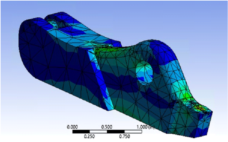
These needs formed the basis upon which we would iterate designs as we started the design process. As my team members proposed designs, I applied motion analysis in SolidWorks and simulated designs in ANSYS software to verify clearance of certan part geometries and simulate strength of each design by measuring resulting forces. Design feedback would usually come through showing an array of simulation results, concluding in suggestions to add material thickness in areas where the simulated tool showed weakness.
Emperical Testing
The third stage involved empirical testing of the physical force required to crimp tubes. We utilized an MTS machine for this testing process, which provided us with data to cross reference forces calculated with formulas and with the ANSYS simulation.
Final Design Review
Once our design had been thoroughly tested and adjusted, we moved on to the fourth stage. This involved creating a Bill of Materials (BOM) and conducting a final review of our design against the initial requirements.
Manufacturing and Assembly
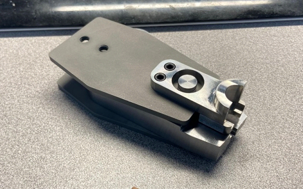
With our design finalized and approved, we proceeded to the fifth and final stage: manufacturing and building the crimping tool. This stage sending our part drawings and BOM to a local manufacturer to be heat treated, machined, and assembled.

