CNC X,Y Pen Plotter
@lifeofasamjohnson #fyp #artistsoftiktok #sketch #fypシ #pendrawing #artwork #drawings #artist #sketches #fyp ♬ original sound - Roshan
About
I discovered my love for CNC in the Summer of 2018. I was an undergraduate engineering student that operated 4 Ton (3900 kg) CNC machines at Rochester Precision Machine in Rochester MN.
A few years later, my old boss at SUBC Inc–Dr. Dan Ericson–gifted me a small CNC router. Best day ever.
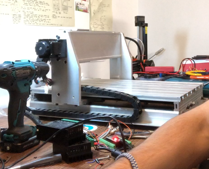
I so badly wanted to use the router, but I didn’t have the budget for parts to cut wood or metal. I then converted the router into an X,Y Pen Plotter.
This post details how I designed fixtures and wrote software for pen holding, image-to-path conversion, and more.
Skills Involved
- Mechanical Design
- Electronics
- Robotics
- Embedded Software Development
- Software Development
Procedure
Converting the Router
I wired the router’s X and Y axis (NEMA-17 Stepper Motors) to stepper motor controllers. I drove the stepper motors with an old laptop power supply.
Creating the 3D printed Z-Axis
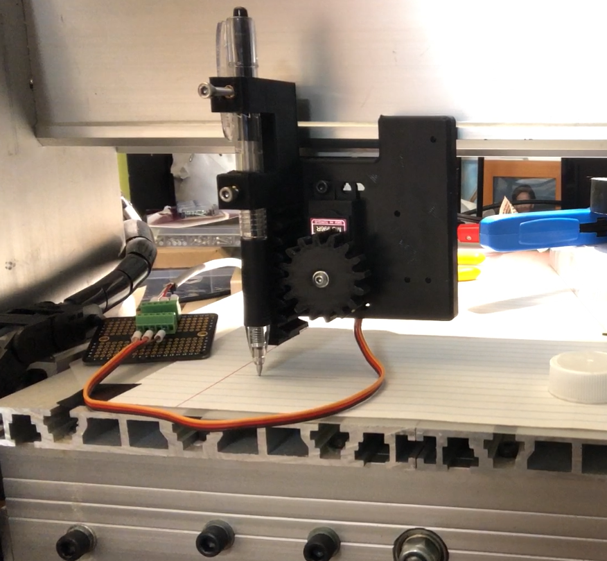
To create the Z-Axis, I 3D printed a fixture with features for a servo, gear rack and pinion to mount to the head of the router. I went through a few iterations to find a design that was rigid when acutating the pen onto paper and quick to print. A ball screw and linear guides would have increased accuracy, but I was more focused on proving this pen plotting concept (and software) would work.
Creating the plotting software & Machine Code
At the moment, I’ve created custom plotting software that converts SVGs–made of bezier curves–into toolpaths. The curves are converted into polygonal lines, which are converted into a series of X,Y coordinates before being scaled to fit on a page that the CNC Router can plot.
Accepting the Machine Code
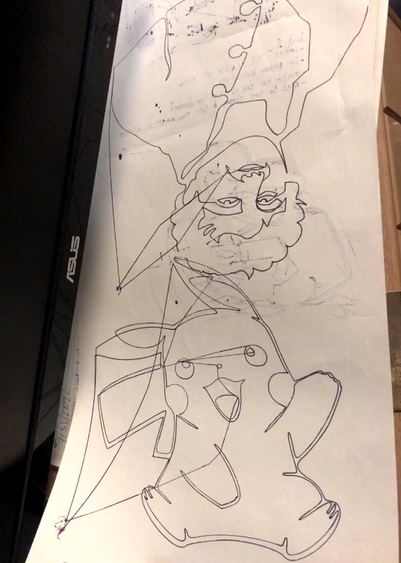
These drawings were made before integrating the Z-Axis →
Not Bad!
It works because the machine code is sent to a ESP32 microcontroller with custom embedded software/machine code that moves the motors to the desired coordinates.
Essentially, once the motors have reached the desired point and moved the Z-Axis accordingly, the embedded software informs the plotting software that it’s ready for the next X,Y coordinate. Commandeered by the plotting software, the router head plots “generated” images.
Trial and Error
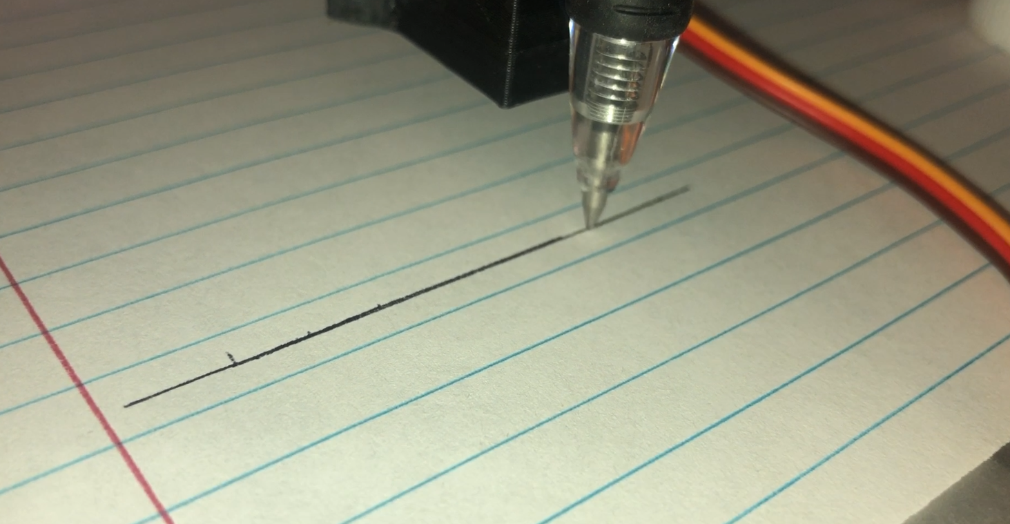
I iterated a few designs to a working 3D printed gear rack and pinion. It took a few tries because of my material choice. The polylactic acid (PLA) filament and my printer doesn’t have a fantastic tolerance or surface finish with the orientation I printed it, but I realized if I minimize the contact area between the rack and it’s rail, it wouldn’t over constraining the part. This allowed for surprisingly fluid and repeatable motion. I don’t have a Keyence or MicoVu system at home but I would measure the repeatability if I could.
With a self-programmed CNC system I don’t know how much the drive screws are slipping with respect to the motor and if there is skew happening due to the rust of the screws and the acceleration programmed in to the controller. As robotic as a CNC pen plotter can be, the imperfections make it surprisingly human.
I’m also in the process of creating a custom plotting software that converts images into hatched tool paths. The software posterizes an image into 4 rasterized colors (4 layers of shading), before programatically separating each color into respective layers. Each “colored” layer is characterized by a set of polygons that make up the contours of the continuous bodies of color. A bounding box is created for each polygon before applying a hatch pattern to it. The space outside the contours, but within the bounding box is negated, creating a “patch” for each polygon.
The polygonal points are converted to bezier curves (and a respective SVG file), which are converted to a series of X,Y,Z coordinate that indicates the next position the router head needs to move and if the pen needs to be moved up or down. Each SVG file is then converted to a CSV to store the “machine code”, which can be sent to the embedded script to move the router head.


